System Setup & Environment
-
Platform: NVIDIA Jetson Xavier NX (P3668-0001)
-
Carrier Board: VECROS JETCORE Carrier Board
-
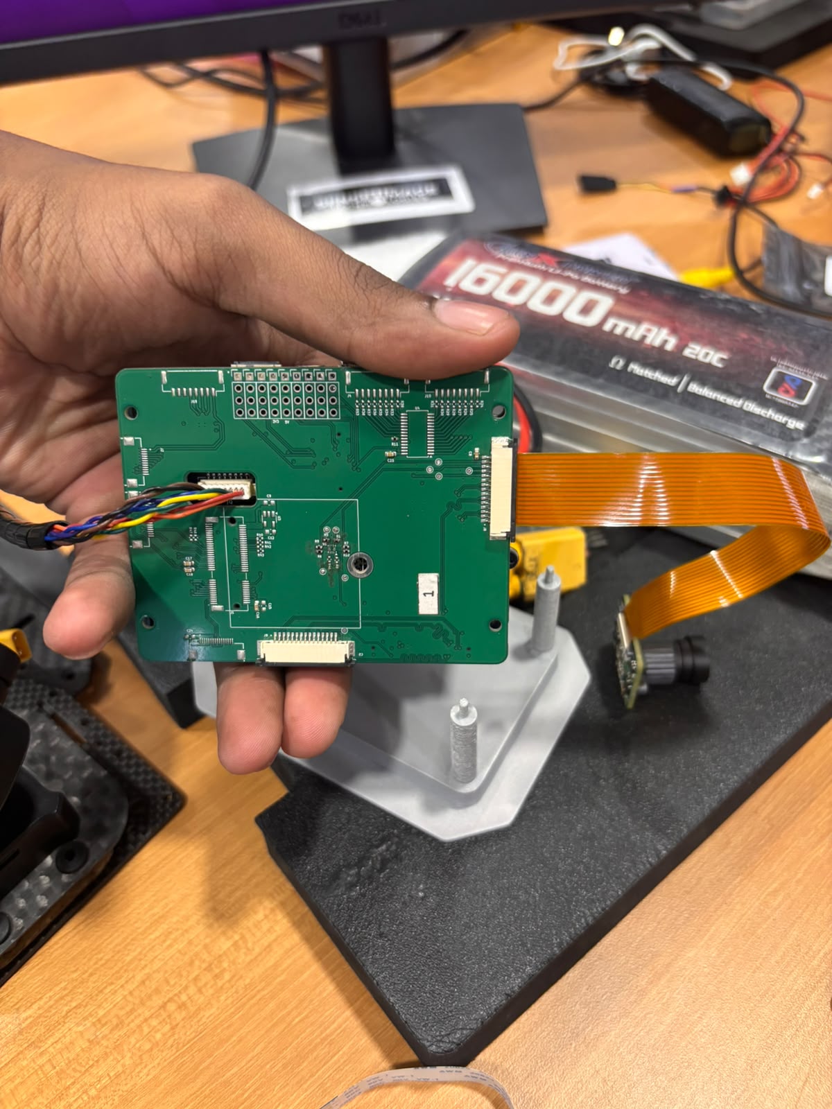
Daughterboard: VECROS Dual-Camera Daughterboard
-
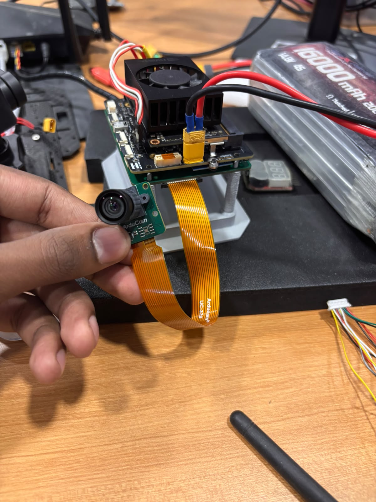
Target Payloads: Arducam IMX477 MIPI CSI Camera, SIYI A8 Mini Gimbal Camera (USB)
-
OS / Environment: L4T 35.6.5 / JetPack 5.1.7 (Kernel:
5.10.216-tegra)
Issue 1: Arducam IMX477 MIPI CSI Interface / Sensor I2C ACK
-
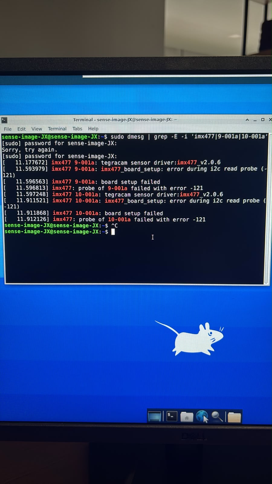
Observed Problem: The Arducam IMX477 does not register or acknowledge on any I2C bus (
0x1areturns NACK /--). -
Hardware & Electrical Measurements Done:
-
Core Power (Pin 22 on FPC / Pin 15 on Daughterboard): Measures a steady 3.40V.
-
Master Clock: Confirmed the camera module utilizes an onboard active 24.000 MHz crystal oscillator (
SCTF 24.000). -
Reset Line (Pin 17 on FPC / Pin 11 on Daughterboard): Driven via Tegra GPIO
PP.05(gpio-432, line 97) at 1.80V; asserting this pin HIGH holds 1.80V on the sensor reset line. -
SCL/SDA Static Pull-Up: Daughterboard Pin 13 (SCL) and Pin 14 (SDA) sit at 3.39V.
-
-
Diagnostic Test (Clock Line Modulation Check):
-
Ran continuous high-rate read loops across all registered adapters (
i2c-1,i2c-2,i2c-9,i2c-10) targeting address0x1awhile monitoring Daughterboard Pin 13 (SCL) with a digital multimeter. -
Result: Pin 13 remained static at 3.390V without any voltage sag or duty-cycle modulation during SoC bus access, indicating the camera connector SCL line is not receiving clock transitions from the Tegra I2C controller.
-
Daughterboard Pin 12 (
CAM_IO1/ Camera Pin 18): Measures 0.00V
-
Issue 2: USB Interface Measurements & Port Bank Discrepancy
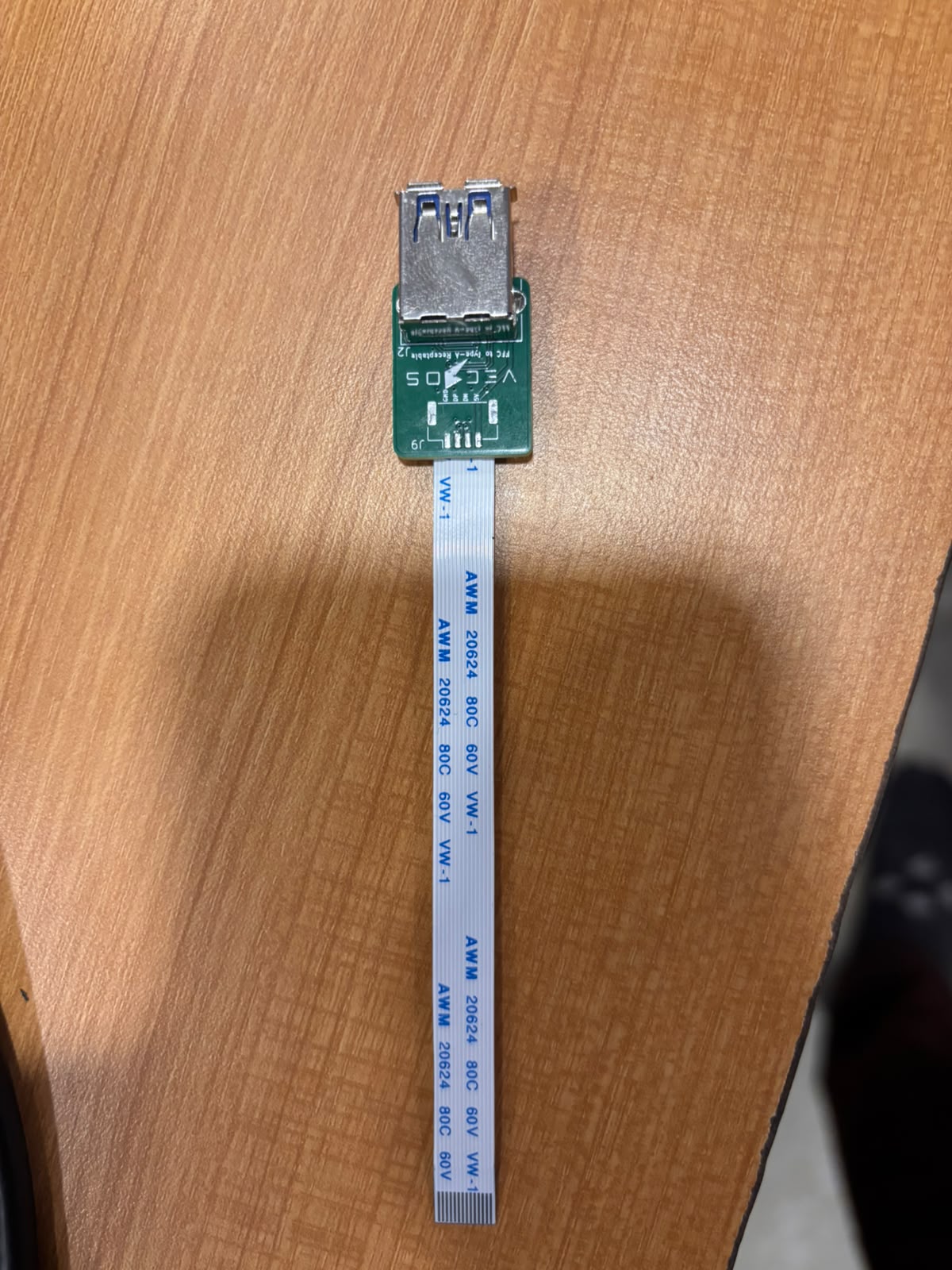
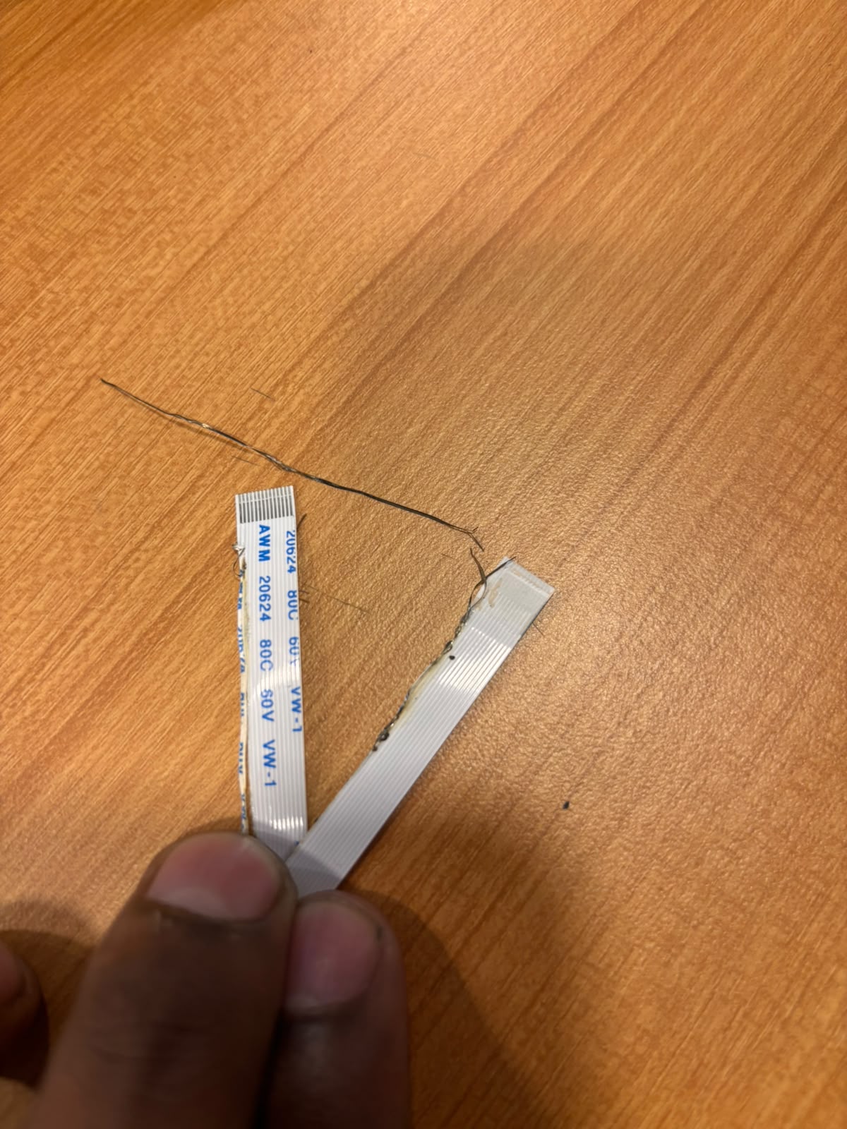
- Observed Problem: Connecting a 14-pin FFC cable to the onboard USB breakout resulted in an immediate high-current short, causing thermal damage to the ribbon cable.
Board Inspection & Next Steps Request
-
Physical Board Inspection / Diagnostic Review: Guidance on sending both the JETCORE carrier board and the dual-cam daughterboard to your engineering facility for inspection, validation of the USB power stages, and trace verification.
-
Schematic / Pinout Reference: Connector pinouts and contact orientation (top vs. bottom contact) for the USB FFC footprint and daughterboard mating headers.
-
BSP / Device Tree Reference: The validated DTS/DTB configuration for camera sensor bring-up on L4T 35.x for this specific hardware revision.